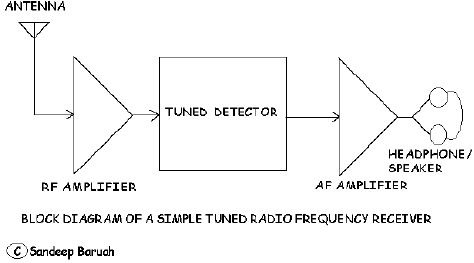
A TRF receiver consists of the following stages:

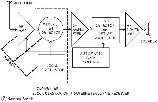
In a TRF receiver a series of loosely coupled tuned circuits are used to increase selectivity and each circuit are ganged so that they resonate at the same frequency. But in a superhet receiver, this principle is not followed, instead, the RF amplifier, mixer and local oscillator are ganged to produce an intermediate frequency.
In a TRF receiver the high amplitude original frequency is demodulated at the detector stage. But in Superhet sets, the IF is demodulated.
In a TRF Receiver, no image frequency is produced. But image frequency is produced in superhet receiver.
In a TRF receiver, selectivity is not constant; the receiver is more selective at the low frequency bands, while less selective at the high frequency end. Because the detector and amplifiers of a superheterodyne receiver can be designed to amplify only intermediate frequency (IF), this type of receiver is more selective and offer high fidelity (exact reproduction quality of the transmitted signal).
In TRF receiver, amplification is not constant over the tuning range. In superhet receiver amplification standard is constant since all the time it amplifies a constant frequency at the IF stages.
The main objective of the superheterodyne receiver is to produce an intermediate frequency (IF) by the process of heterodyning or beating.This can be accomplished when two frequencies are mixed to produce the beat frequency. In superhets, the IF is usually 455 kHz which is selected because the broadcast band begins above that frequency. So, if we imagine a situation when the RF amplifier is tuned to receive a 800 kHz broadcasr signal, the local oscillator must be tuned to 1255 kHz which will result in an IF of 455 kHz (1255-800 kHz=455 kHz).Since we have to tune the RF amplifier section throughout the entire broadcast band, the frequency of the local oscillator must also vary in a manner that it always maintains a gap of 455 kHz. To achieve this condition, the Local Oscillator and RF Amplifier section are ‘ganged’, i.e. their tuning condensers are connected/ganged mechanically in such a way that when we tune the variable capacitor in the RF section, the variable capacitor in the local oscillator also changes its value, it ‘tracks’ the frequency to which the ‘Aerial Circuit’ is tuned and remain seperated from the tuned frequency by 455 kHz up.
The Intermediate Frequency (IF), which is a considerably low frequency is being used, because-
it is a suitable frequency to achieve amplifying efficiency.
It provides better selectivity.
It provides better sensitivity throughout the broadcast band.
It provides uniform sensitivity as well as uniform selectivity.
Selectivity is the measure of the ability of a radio receiver to select a particular frequency or particular band of frequencies and rejecting all other unwanted frequencies. But higher selectivity does not necessarily make a better receiver. For instance, a ‘broadcast signal’ consists of the carrier frequency and its two side bands. In a situation where a carrier frequency of 800 kHz is modulated with a 5 kHz (5000 Hz) tone, the sum of the carrier and the audio frequency results in the Upper Side Band (USB) of 805 kHz. The difference of carrier and audio frequency results in a Lower Side Band (LSB) of 795 kHz.So for proper reproduction of the broadcast signal at a particular carrier frequency, the receiver must receive (select frequencies from 795 to 805 kHz. A receiver more selective than this would reject a part of the frequencies thus proper reproduction would be hindered.

So a Local Oscillator and a Mixer circuit are combined, where, by the process of ‘heterodyning’, i.e. ‘beating’, the ‘Intermediate Frequency (IF)’ is obtained.If the RF Amplifier section selects and amplify a signal of 800 kHz, then the local oscillator produces a frequency of 1255 kHz. By mixing both the frequency at the mixer stage, a difference of frequency of the value 455 kHz is obtained (1255-800=455 kHz).
Intermediate Frequency (IF) Amplifier:
The 455 kHz IF is fed to the IF amplifier through an IF transformer. The circuitry of the IF section is so designed and tuned so that it gives the optimum gain at that particular IF frequency.
Detector/Demodulator and 1st Audio Frequency Amplifier stage:
The Amplitude Modulated (AM) IF is demodulated and detected. A diode working as rectifier solves this purpose. The triode/transistor amplifies the audio signal and the volume control potentiometer system controls the intensity of sound.
AF Power Amplifier:
This section further amplifies the audio signals which is finally fed to an output transformer which matches the impedance of output stage with the speaker (in modern transistor receivers, the necessity of output transformer is eliminated).
Automatic Gain Control is a most needed part of superhet circuitry.
A disadvantage of manual gain control (volume control) with a receiver is that it can’t provide constant output under all conditions. If a receiver is tuned from a weak signal to strong signal, its output must increase intolerably. This would then require readadjustment of the volume control. Similarly, when a receiver is tuned to particular signal the output level can vary widely if the input signal strength fluctuates as a result of fading and adjustments of the volume control has to be done. Since such signal fluctuations are rapid, constant readjustment of volume control would be necessary which is impractical. This is where AGC or AVC comes into picture and is used in addirion to the manual control.
All AGC or AVC (Automatic Volume Control) circuits perform two basic funtions;
The first of these is to develop a DC (Direct Current) which is proportional to the receiver input signal all the time.
The AGC voltage is applied to the RF and IF stage of the receiver where it serves as a Bias voltage.In this way the AGC voltage controls the gain of RF and IF stages, and therefore the overall gain of the receiver. When the signal level at the receiver input increases, the AGC voltage increases proportionately. Consequently, a larger bias is applied to the IF and RF stages and their gain is applied to the IF and RF stages and their gain is reduced. The receiver output thus remains relatively constant instead of increasing in accordance with the input signal strength and vice-versa. In valve type RX (receiver), the grids of RF and IF portions valves are biases by negative voltage. While in a transistor it depends on transistor type.
The squelch circuit or Q (Quieting) circuit is a circuit which is controlled by AGC or AVC voltage. The modern high gain receivers shows a disadvantage without it, that is, without a squelch circuit, annoying buzzing and cracking sounds are heard over the loudspeaker in absence of input signal. So a circuitry is arranged in such a way that AF gain is kept reduced in absence of input signal from the antenna.
With no signal there is no Negative AGC voltage, and the squelch tube allows current to flow through it then passing through R3 to the +250 V point. Thus R3 produces a DC voltage drop across it which is more negative at midpoint than at the bottom being in series with the amplifier grid circuit, tube past cutoff, preventing it from functioning.
When a signal is received, AGC or AVC voltage biases the squelch tube to ‘cutoff’, stopping plate current flow. Consequently, the voltage drop across R3 ceases, allowing the AF amplifier tube to act in a normal manner.
The intermediate stage (mixer+local oscillator) of a superhet radio set produces an Intermediate Frequency (IF) due to the beating of RF input frequency and Local Oscillator Frequency. This frequency is obtained by deducting the RF input from the tuned circuit from that of Local Oscillator Frequency. So, while receiving a 800 kHz RF signal, the Local Oscillator is made to oscillate at a frequency of 1255 kHz which results in an Intermediate Frequency (IF) of 455 kHz (which is accepted as a standard in almost all the Broadcast band receiver circuits); but it is found that in case of comparatively less selective receiver, if a broadcast frequency 455 kHz up, from the 1255 kHz local oscillator frequency manages to intrude the RF tuned circuit even to a little extent, then another difference of frequency equal to intermediate frequency results; viz. 1710-1255=455 kHz. But this ‘455 kHz’ being generated from a signal frequency having different audio information causes adverse effect at the audio end of the receiver. The intelligence of both would be present in the speaker at the same time making the sound reproduction is unintelligible.
Prevention of Image Frequency:
By highly selective RF tuned amplifier;By using an IF which is convenient to use and at the same time seperation between desired and image signals is made large. Possibility of image frequency generation is greater in a receiver designed for an IF of 175 kHz than a receiver using an IF of 455 kHz.
A S-meter is a visual indicator of signal strength. A simple S meter consists of a milliammeter in series with an RF or IF amplifier plate/collector circuit.With no signal, there is no AGC bias voltage and maximum plate current flows.With a signal, the AGC biases the tube, reducing the plate current and the indication on the meter. The stronger the signal, the less current the meter indicator signifying a strong strength.
To change the second detector from a rectifying or envelope detector to a heterodyne detector to receive A1A (Continuous Wave Morse Code), A2A (Modulated CW Morse Code), J3E (Single Side Band), the Beat Frequency Oscillator is turned on. It is a variable frequency oscillator using a Hartley, Colpitts or Armstrong circuit. It is tunable to the Intermediate Frequency and one or two kilohertz higher and lower. It heterodynes with any signal coming through the IF strip, producing an audible beat frequency in the detector. Both the BFO and LO (Local Oscillator) must have good frequency stability.
The radio sets available in the market for general public are designed to receive Amplitude Modulated (AM) or Frequency Modulated (FM) broadcasts only. But the ham radio operators use a very efficient mode of transmission called Single Side Band (SSB) transmission. The power of a ham radio station is also very low ( usually not more than 100 watts) in comparison to the broadcast station (which use power in the kilowatts range). In fact many of the broadcast band radio receivers available in the market also covers some of the frequencies which are allotted to the ham radio stations. A 4 band radio set (inclusive of the Medium Wave band) can be expected to cover some popular ham radio frequencies like 7 to 7.1 MHz (i.e. 7000 to 7100 kHz), 14 to 14.350 MHz (i.e. 14,000 to 14,350 kHz) and 21 to 21.450 MHz (i.e. 21,000 to 21,450 kHz). This kind of receiver can be improvised to receive ham radio transmissions with very little effort.

First, we will need an outdoor aerial. Because, these radio sets are not sensitive to receive low power transmissions. Majority of the hams use power below 100 watts (a broadscast station may use 4000 or 5000 watts of power!). A novice ham radio operator may be found to be operating with a power as low as 0.5 watt!
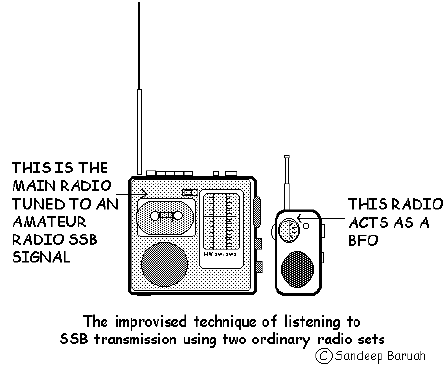
Ham radio conversation if heard on an ordinary radio set sounds like the ‘Duck quacking’. There is no intelligibility in the audio. As already mentioned, our ordinary radio sets are meant to receive AM signals only and not to receive SSB signals-a separate unit is so required at the ‘Detector’ stage of the AM receiver, which is nothing but a stable ‘Frequency Generator’ (RF Oscillator), called the ‘Beat Frequency Oscillator’ (BFO). The BFO is used to introduce a ‘Local Carrier Frequency’ (frequency of the carrier is 10 to 20 Hertz within that of the transmitter carrier frequency which is suppressed at the transmitter of the ham radio station willingly in order to save power). Another popular technique of receiving ham radio stations on an ordinary receiver set is to employ two radio sets. In this improvised technique, one radio set acts as the BFO. The radio sets are just kept very close together. The volume control knob of the radio set which we intend to use as a BFO should be kept at its minimum. Usually a two band (one Medium Wave and one Short wave) AM pocket receiver can be suitably used as a BFO. The first step is to locate a ham radio transmission over the main radio receiver (search for the “duck quacking” like audio) tuned to a ham frequency (say in the 40m or 20m band, i.e. 7-7.1 MHz or 14 to 14.350 MHz respectively). Once a strong ham station has been detected, the next step is to bring the pocket receiver (whose volume is kept at minimum) near to the main receiver. The pocket radio set should also be tuned to a frequency near to the frequency in which the ham transmission is received. By this way, frequency generated by the local oscillator of the pocket radio can be made to produce the heterodyne effect in the main receiver making the ham transmission intelligible. This technique of course requires your patience. The first attempt should not become the last attempt!